


DTFPartsStore.com
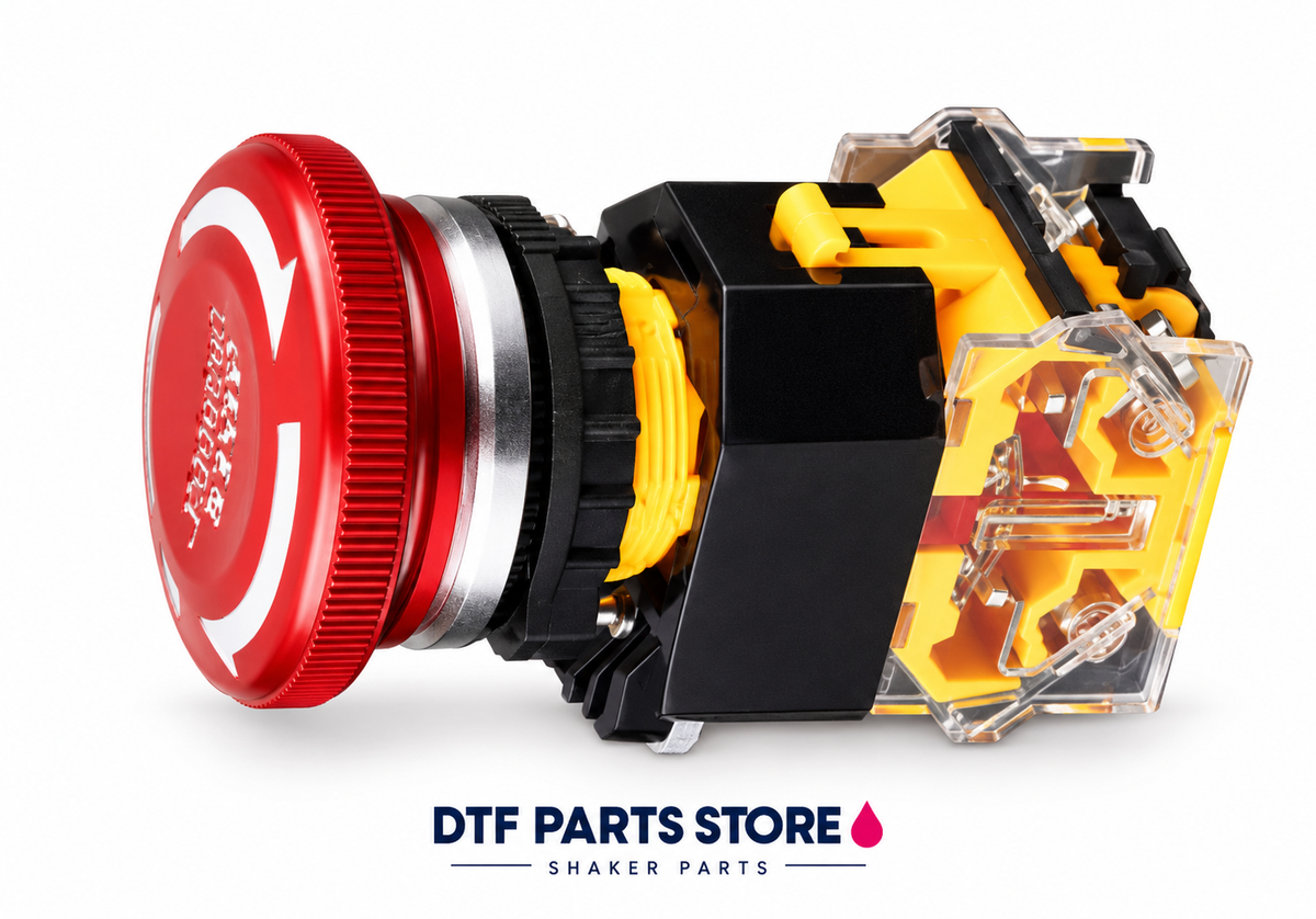
Shaker Emergency Stop Switch — 1NO + 1NC
Shaker Emergency Stop Switch — 1NO + 1NC
Couldn't load pickup availability
Replacement emergency stop switch with one normally open and one normally closed contact. Match panel fit, contact configuration and the machine safety circuit before ordering.
Specifications
- Contacts: 1 normally open + 1 normally closed
- Application: emergency stop control
Compatibility
Listed for the H6501 shaker parts system. Machine revisions vary. Compare your original part, electrical ratings, dimensions and connections before purchase. Contact DTF Parts Store with photos if you need help checking compatibility.
What is included
One replacement component as listed. Other machine parts are not included.
Availability
Currently out of stock. Contact us for restock updates.
Image is a branded illustration based on the supplier reference. Confirm the actual part markings, connections and dimensions before ordering.
DTF Parts Store • Repair supportInstallation & troubleshooting
View safety steps and replacement checks
Know what to check, how to prepare safely, and what your technician should verify for this electrical control. Machine layouts and wiring vary by model.
Shaker Emergency Stop Switch — 1NO + 1NC
Match before replacing:
Exact part / revision • ratings • terminals
Power, heating or control does not operate correctly. A tripped protective device can signal an underlying fault; do not repeatedly reset it or bypass protection.
Safety first — before access or repair
Follow the machine’s shutdown procedure. Isolate all power sources and prevent restart using the approved lockout procedure. Control stored energy and let heaters cool fully. An authorized person must verify isolation before work starts. The power button or emergency stop alone does not isolate electrical energy.
Electrical work, heaters and safety controls require a qualified technician. Never work inside a live cabinet, bypass guards or safety devices, or reach into moving rollers or fans. Follow the machine manual and powder/ink safety data sheet for required protective equipment.
Stop & isolate
Shut down, isolate supplies, prevent restart, control stored energy and verify the machine is safe to access.
Inspect & match
Do not open an energized cabinet. A qualified technician must isolate every supply, control stored energy and verify the circuit is de-energized before inspecting connectors or components.
Replace correctly
Qualified technician only. Use the exact machine schematic and component instructions to match ratings, terminal assignments, board revision and protective functions. Never copy wire colors alone, bridge a safety circuit or increase a breaker rating to stop tripping.
Verify operation
The technician must restore terminal covers and guards and test the affected function and safety controls using the manufacturer’s procedure. For an emergency stop or protective device, do not return to service until its protective function is verified.
Stop and get help if…
You find burned wiring, repeated breaker trips, damaged safety controls, uncontrolled heating, ink on electronics, a mismatch in ratings, or a diagram that does not match the machine. Keep the machine out of service until a qualified technician resolves the fault.
What to send for model-specific help
Send the machine model and serial label, a clear photo of the original component and its markings, your symptom, and the relevant service-manual page. Take internal photos only after safe isolation by an authorized person. Do not unplug or move wires just to photograph them.
Need the procedure for your machine?
Send your model and original part photos so we can help confirm compatibility and the correct service reference.
Get part-specific help →This is a service planning overview. Use the exact machine and component manuals for removal, wiring, torque settings, calibration and commissioning. It is not a model-specific wiring diagram.